
Inhaltsverzeichnis
- Real air flow or just a beautifully painted picture?
- CFD is not an end in itself, it is a tool for knowledge.
- The real problem: three typical misunderstandings in the industry
- Why a real CFD in exhaust air technology is so complex
- A practical example: When the air doesn’t do what you think it does
- Why flow models are not automatically reality
- The crucial point: aerosol simulation makes the difference
- CFD in exhaust air technology is also available as an AI podcast episode
- What this means for planners and operators
- Conclusion: Real CFD creates clarity. Colorful arrows often only create an impression.
- Follow us on social media
CFD in exhaust air technology: Why colorful arrows are far from the truth. A lot is shown in exhaust air technology. But not everything that looks like technology actually has anything to do with reality.
CFDs in particular are often associated with big promises. Some say that CFD is useless in this area. Others show colorful graphics, thermal images or simple arrow diagrams and give the impression that this is already a reliable flow analysis.
And still others simulate the air flow, but save themselves the decisive next step: the additional consideration of airborne aerosols.
CFD stands for Computational Fluid Dynamics. In simple terms, this means the following: Computers, physical models and mathematical processes are used to calculate how air or fluids really move. Or in other words, not estimated, assumed and invented, but calculated.
This is exactly where the problem begins.
Because if you really want to understand air pollution control, capture and separation, you can’t be satisfied with pretty pictures. The decisive factor is not whether a representation looks convincing. What matters is whether it depicts the real air flow and the real behavior of airborne particles.
Real air flow or just a beautifully painted picture?
The central question is:
Do we see a real, reliable flow analysis? Or do we just see a colorful picture with arrows?
The difference is greater than many people think.
Real air flows are investigated in scientifically equipped flow laboratories. There, experts work with modern CFD software, validated models and often also with metrological tests. It is precisely this combination of simulation and reality that is crucial.
Graphics programs, on the other hand, quickly produce colorful images with arrows. These often look technical. However, they are often based on assumptions that have neither been simulated nor checked by measurement.
The problem with this is that such representations shape decisions. And in practice, this can be expensive, inefficient or even dangerous.
CFD is not an end in itself, it is a tool for knowledge.
CFD stands for Computational Fluid Dynamics, i.e. numerical flow simulation. When used correctly, CFD is a powerful tool. It helps to visualize, understand and optimize air flows in complex systems.
In the automotive industry, this approach has been a matter of course for years. Nobody there would want to solve an aerodynamic problem with a few drawn arrows.
Unfortunately, this is not yet the case everywhere in ventilation technology.
The benefits are clear: with a good CFD analysis, flows in air outlets, capture devices, hoods, separators and complete rooms can be examined in detail. Small design changes can have a major impact. This is precisely why CFD is so valuable in product development and sophisticated planning.
The real problem: three typical misunderstandings in the industry
1. “CFD is useless in exhaust air technology”
You hear this statement again and again. Usually not because it is technically correct, but because the effort is spared.
Reliable CFD analysis takes time, expertise and computing power. Above all, it requires proper modeling, experience and the willingness to critically question results.
Those who shy away from this effort quickly come to the convenient conclusion that CFDs are unnecessary.
The opposite is the case.
Especially in exhaust air technology, CFD helps to make errors visible that you would never recognize with the naked eye or with simple assumptions. If you only think you know how the air flows, you are quickly heading in the wrong direction.
2. thermal image is not the same as CFD
One particularly problematic point is the confusion of thermal images with flow simulations.
A thermal imaging camera can visualize surface temperatures or thermal effects. This can be useful in certain applications. But a thermal image is by no means a CFD analysis.
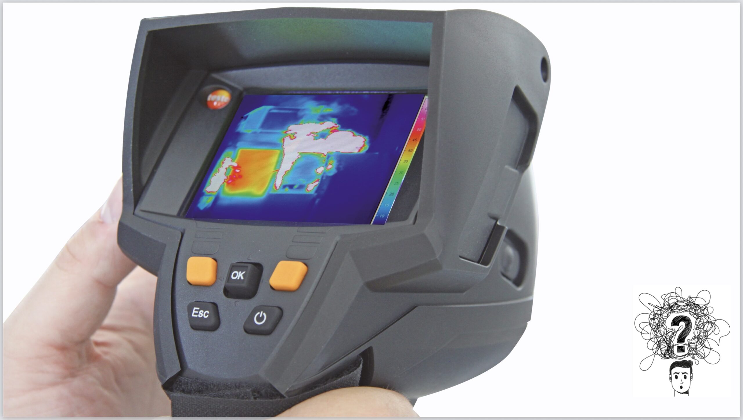
Nevertheless, in practice, illustrations are repeatedly shown that are intended to appear technical, but in reality do not provide any reliable information about the real air flow.
That is dangerous. Because it creates certainty where there are actually still unanswered questions.
3 CFD in exhaust air technology: air flow alone is not enough
A third misunderstanding is particularly serious:
Some people only look at the air flow and then act as if they automatically know what the airborne aerosols are doing.
But air flow and particle trajectory are not the same thing.
Of course, you first have to understand how air flows. But if the aim is to separate aerosols from an air flow, then it is not enough to just look at the air. You also have to simulate how different particle sizes behave in the system.
It is precisely this step that is often omitted because it is more time-consuming.
The result is then only half the truth.
Why a real CFD in exhaust air technology is so complex
Many people underestimate what is behind a really good CFD analysis.
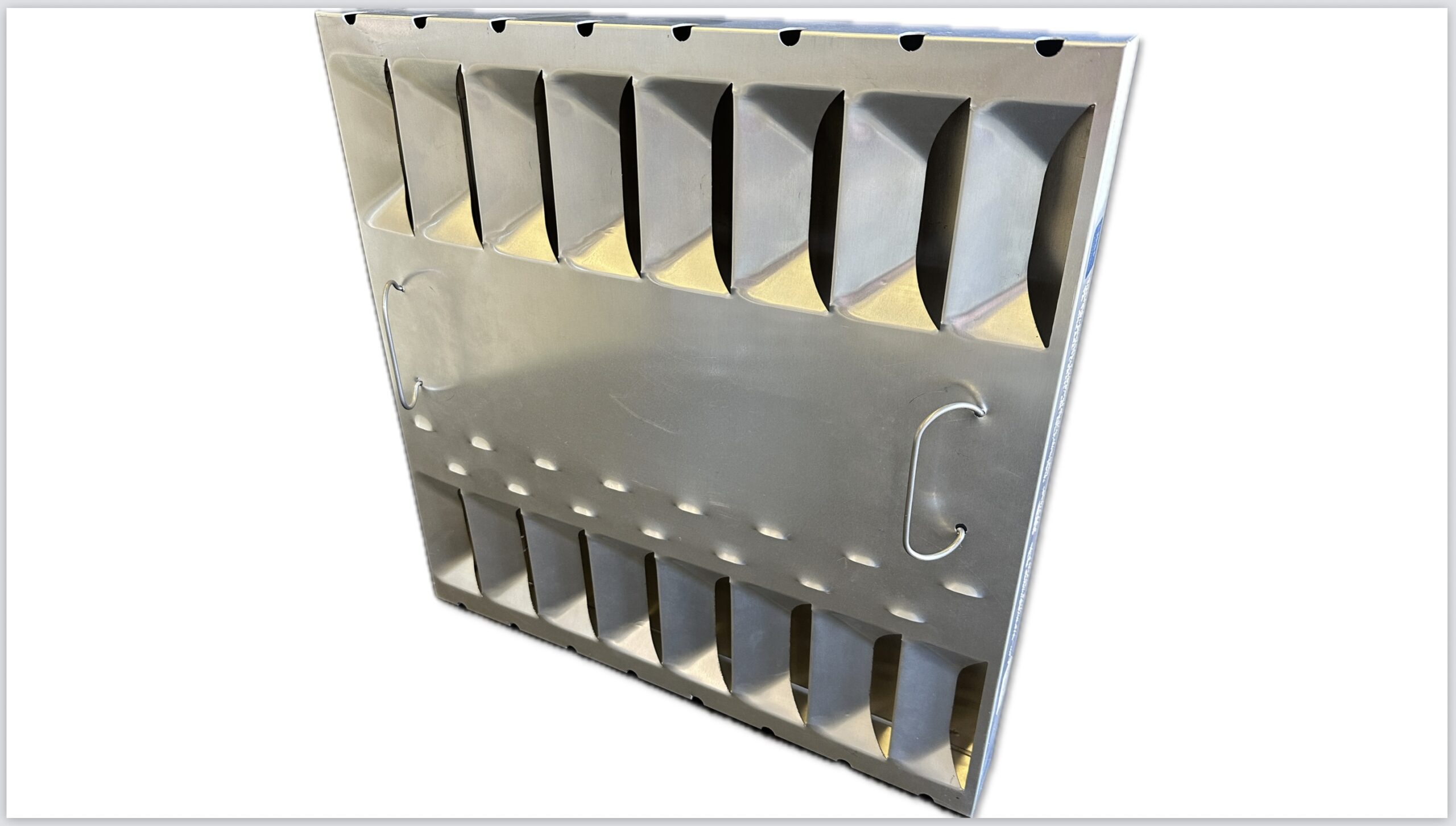
It is not enough to have a 3D model of a component. For a flow simulation, you don’t just need the visible product, but above all the areas in which the air moves. So you have to model the cavities, flow channels, nozzles, outlet areas and interior spaces.
In other words:
It’s not the sheet metal that matters.
What matters is the space in which the air flows.
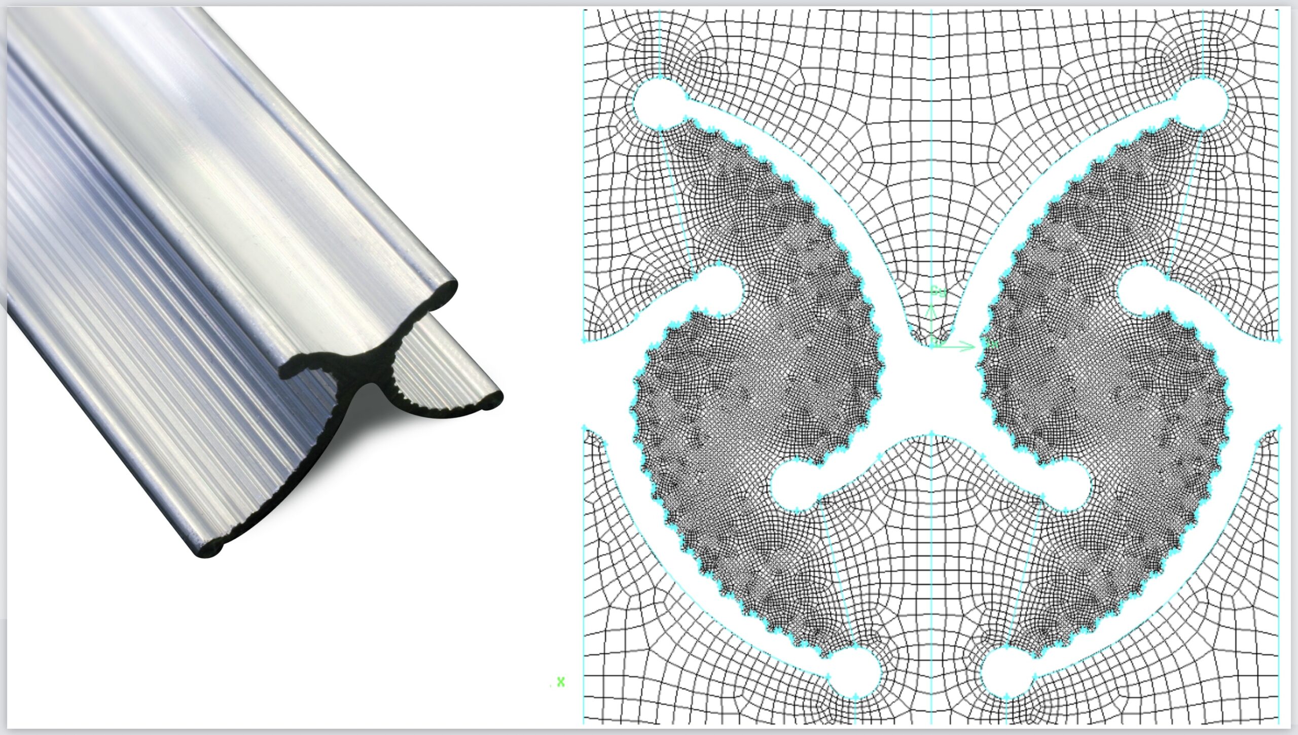
Only then is a computational mesh applied to this model. In many cases, this mesh consists of hundreds of thousands or even millions of volume elements. Cube by cube, it is then calculated how the air moves, at what speed it flows and in which direction it changes.
This is not a “colorful picture”.
That is hard development work.
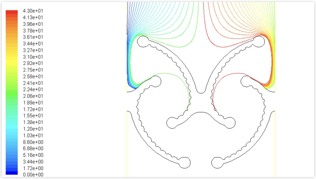
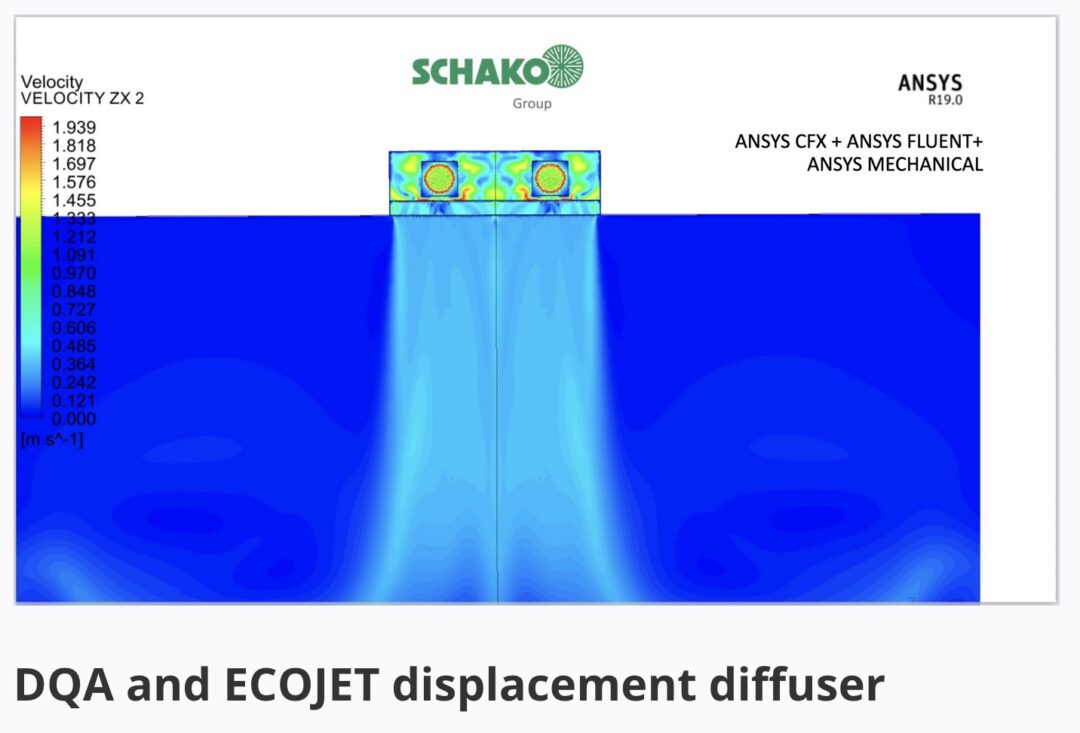
A practical example: When the air doesn’t do what you think it does
This is precisely one of the biggest advantages of CFDs.
Many assumptions seem plausible. Some have even been firmly anchored in people’s minds for years. And yet they can still be wrong.
This was also the case when developing air outlets and detection systems. What looks logical in a sketch doesn’t necessarily work in reality.
An arrow is quickly drawn.
A functioning flow is much more difficult.
Even small changes to an air diffuser can result in air remaining on the ceiling or “popping” downwards unintentionally. In the case of displacement outlets for commercial kitchens, for example, it has been shown that the actual supply air flow can be significantly different than originally assumed.
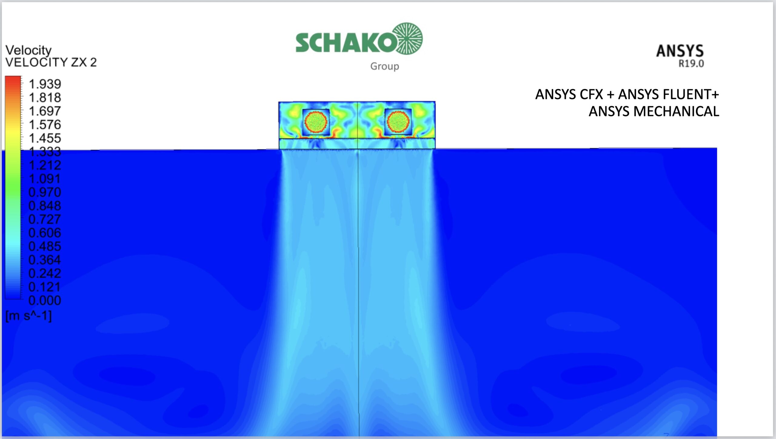
It was only through CFD and subsequent validation in the flow laboratory that it became clear what was really happening. On this basis, the diffuser could be further developed in a targeted manner.
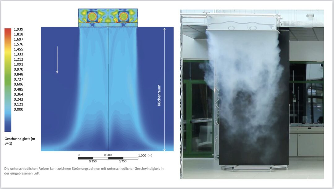
This is the difference between assumption and realization.
Additional information on CFD analysis of displacement outlets can be found here in another blog article (please click on the picture):
Why flow models are not automatically reality
Standards, guidelines and technical presentations all too often show very simplified flow models. Such models are useful. They help to explain relationships and derive calculations.
But they are models.
And a model is not automatically reality.
Commercial plans and projects in particular often show highly simplified representations, ascending delimited thermals, immediate detection, simple and orderly flows. In reality, things often look quite different. There are disturbances, turbulence, components, boundary conditions, doors, movement of people and many other influences.
This is why it is so important to base planning not just on symbolic images, but on reliable studies.
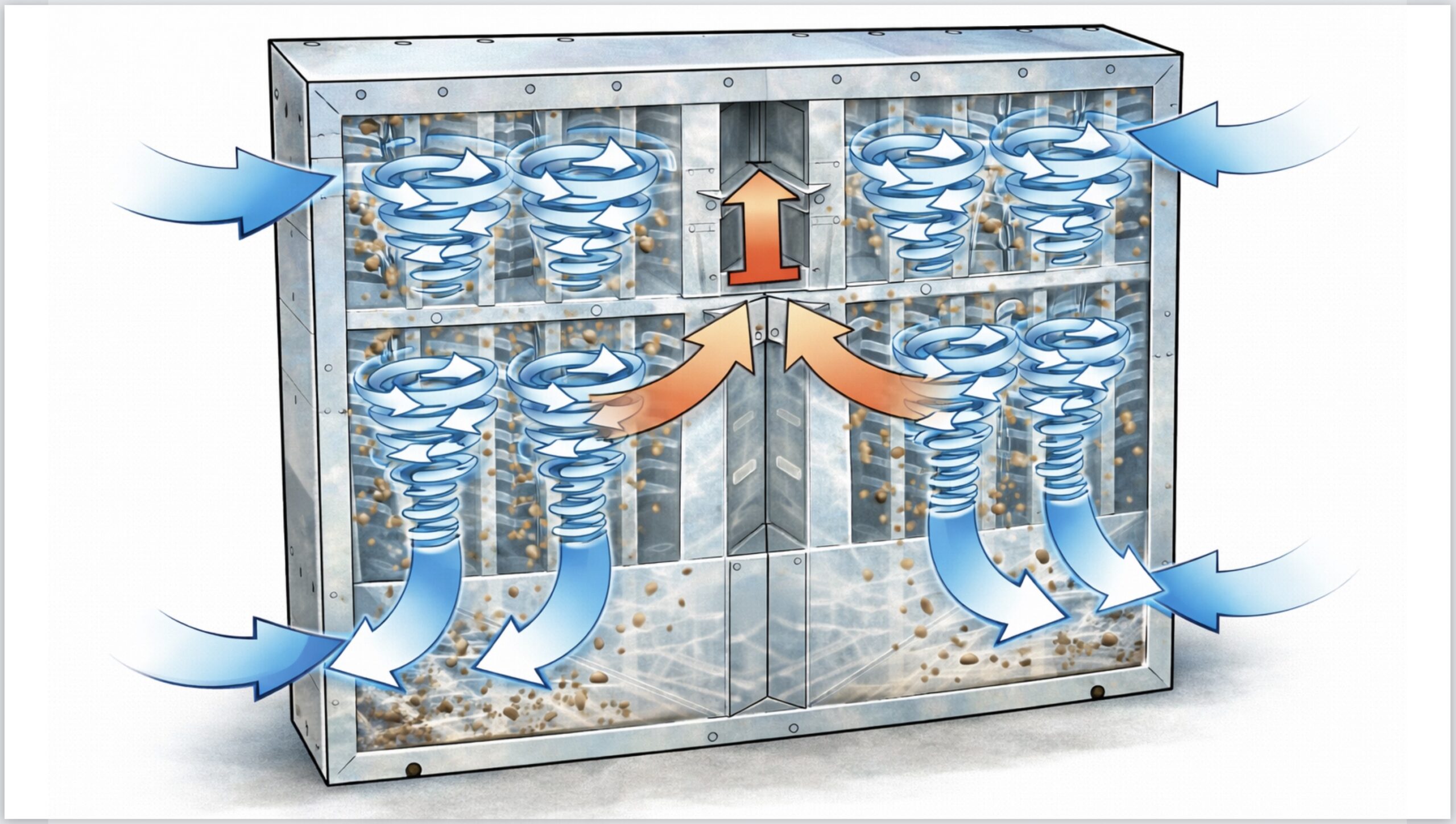
The crucial point: aerosol simulation makes the difference
It becomes particularly exciting when we look not only at air, but also at airborne particles, droplets or aerosols .
Because a separator should not simply move air. It should separate particles from the air flow.
This is precisely why the additional CFD (Computational Fluid Dynamics) analysis of the particle paths is so valuable. It shows where aerosols separate from the air flow, where separation really takes place and where design changes can have a major impact.
This can lead to surprising findings.
What should theoretically happen on a certain surface sometimes happens somewhere else in reality. Only the combination of air flow analysis and particle observation shows which geometry actually leads to better separation.
Those who skip this step are often optimizing in the wrong place.
CFD in exhaust air technology is also available as an AI podcast episode
You can listen to the episode directly here:
What this means for planners and operators
This is an important message for planners, specialist companies and operators:
Not every technical representation is reliable.
Not every simulation is complete.
And not every statement about air routing and capture is automatically correct.
It is therefore worth taking a closer look:
- Was CFD really used?
- Was only the air flow simulated or also the aerosol?
- Is there comprehensible modeling and reliable results?
- Have findings been verified by measurement?
- Or does it just look technical?
This depth makes the difference between show and substance, especially in demanding applications in kitchen ventilation, air purification or mechanical engineering.
Further information on efficient aerosol separators:

Conclusion: Real CFD creates clarity. Colorful arrows often only create an impression.
CFD (Computational Fluid Dynamics) is not a luxury in exhaust air technology. And CFD is not a marketing gimmick either.
Used correctly, CFD is a crucial tool for understanding air flows, improving systems and optimizing the separation of airborne aerosols.
The problem is not CFD – Computational Fluid Dynamics.
The problem is false simplifications, incomplete considerations and technical presentations that promise more than they can really prove.
Anyone who takes responsibility for ventilation technology and air pollution control should therefore not be dazzled by colorful pictures. What really matters is what the air does. And even more important is what the aerosols really do.
Because in the end, it’s not the most beautiful graphics that count.
In the end, it’s the physical truth that counts.